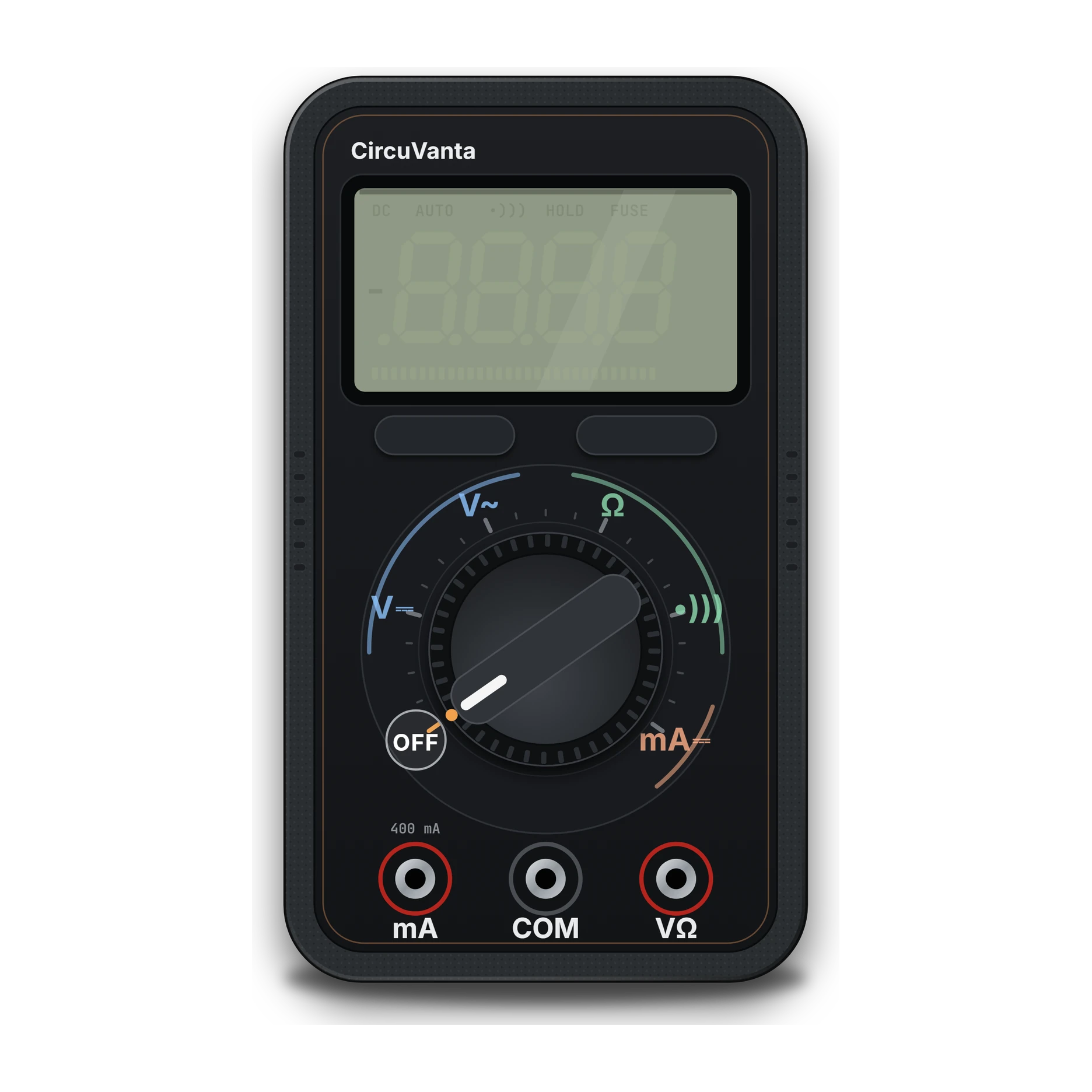
- 1LCD screen · auto range
- 2Function keys
- 3Rotary range switch · V, Ω, continuity, mA
- 4COM socket (black probe)
Palm-sized handheld body
Multimeter
The stethoscope of electricity; it measures the voltage, current and resistance of a circuit.
Shows with a number whether a battery or a wire is good; you find the fault.
In a repairer's bag; used for battery tests and wire checks at home.
A handheld device with a display and a rotary knob in the middle; it has two probes, red and black, and three input jacks.
Plug the probes into the right sockets; do not measure voltage at the current input, or the fuse blows and it becomes a short circuit.
A handheld tool that measures many quantities, mainly voltage, current and resistance. Voltage is measured in parallel with the circuit, current in series. Continuity mode tells you with a beep whether a connection is broken.
IEC 60617: the drawing style used in Türkiye and Europe.
- Voltage (DC/AC)
- From mV to hundreds of V
- Current
- DC current, mA range (up to 400 mA)
- Resistance
- From Ω to MΩ
- Continuity
- Beep at low resistance
- Diode test
- Shows the forward voltage (≈0.6 V for silicon)
- Safety
- Mains measurement is outside this app's scope
- Example part
- Auto-ranging digital multimeter
Part health checks
Pick a part, set the range and the probes, and measure to check that it is in good shape.
Resistors
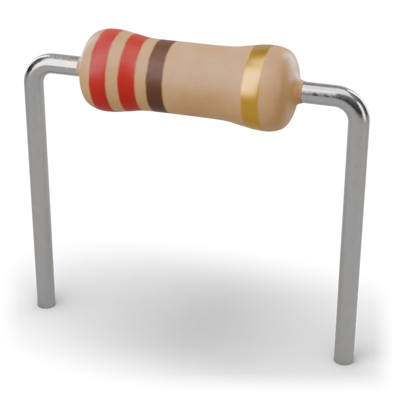 Carbon film resistorΩ · Resistance
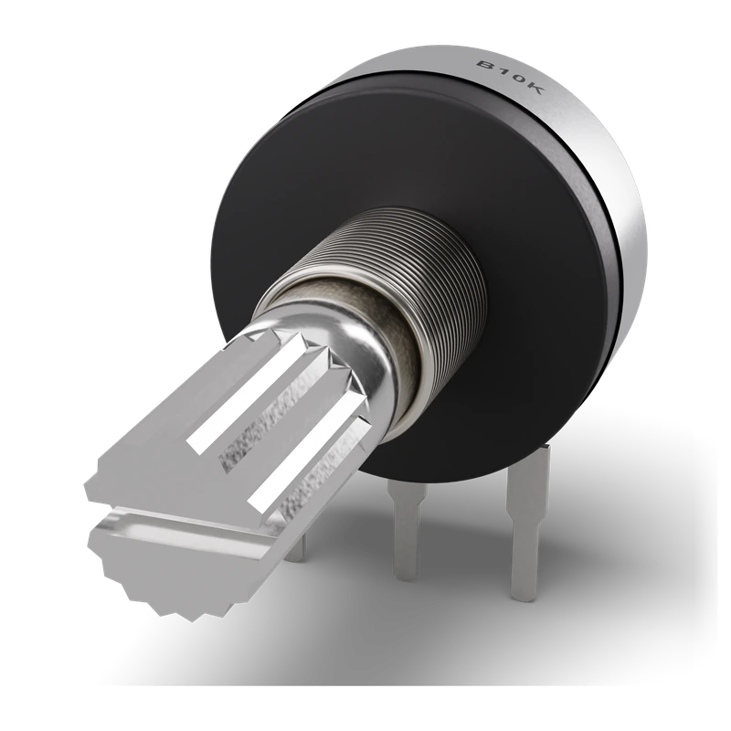 PotentiometerΩ · Resistance
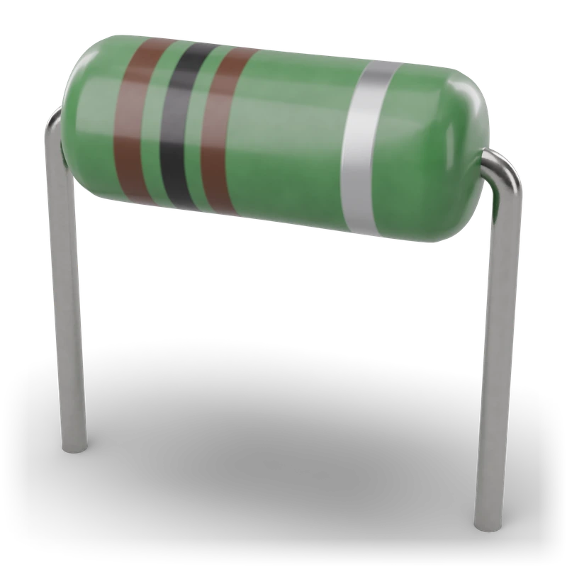
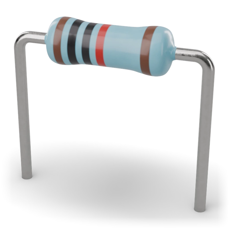 Metal film resistorΩ · Resistance
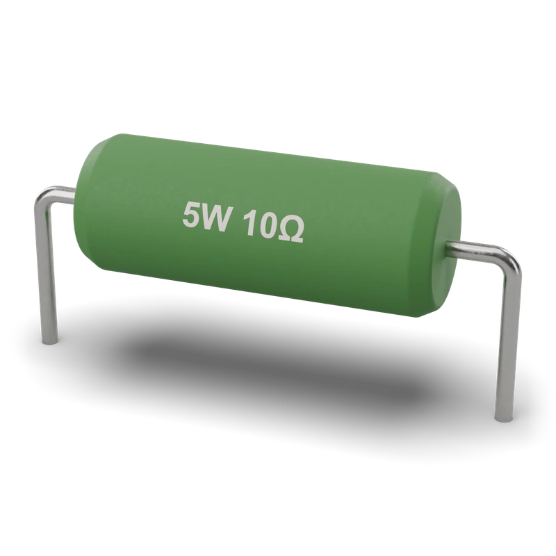 Wire-wound resistorΩ · Resistance
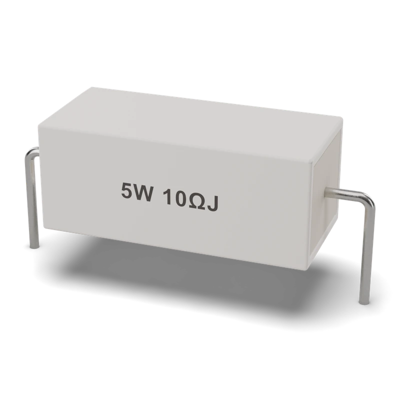 Cement (power) resistorΩ · Resistance
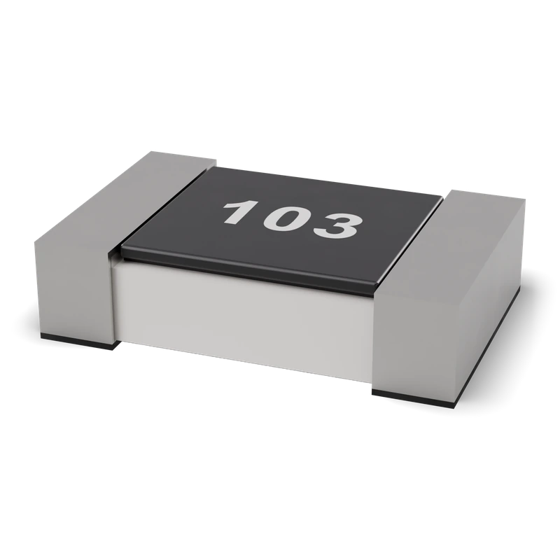 SMD chip resistorΩ · Resistance
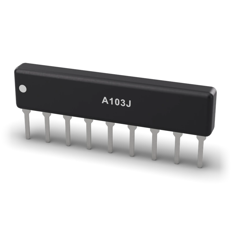 Resistor network (SIP)Ω · Resistance
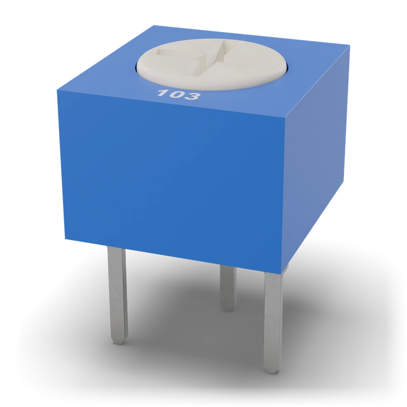 TrimpotΩ · Resistance
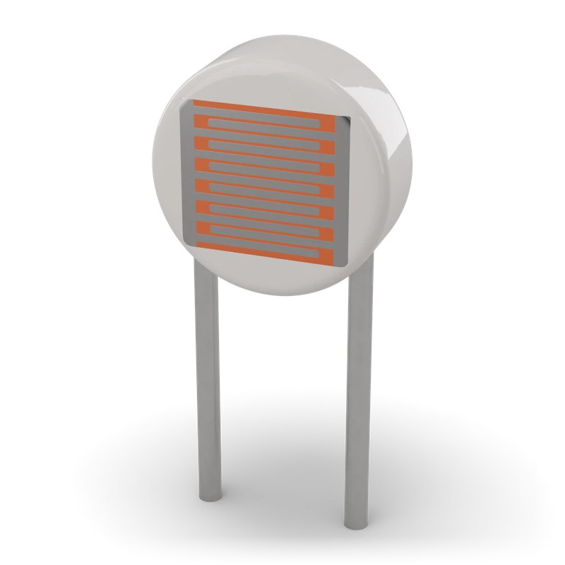 LDR (photoresistor)Ω · Resistance
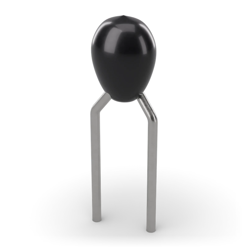 Thermistor (NTC/PTC)Ω · Resistance
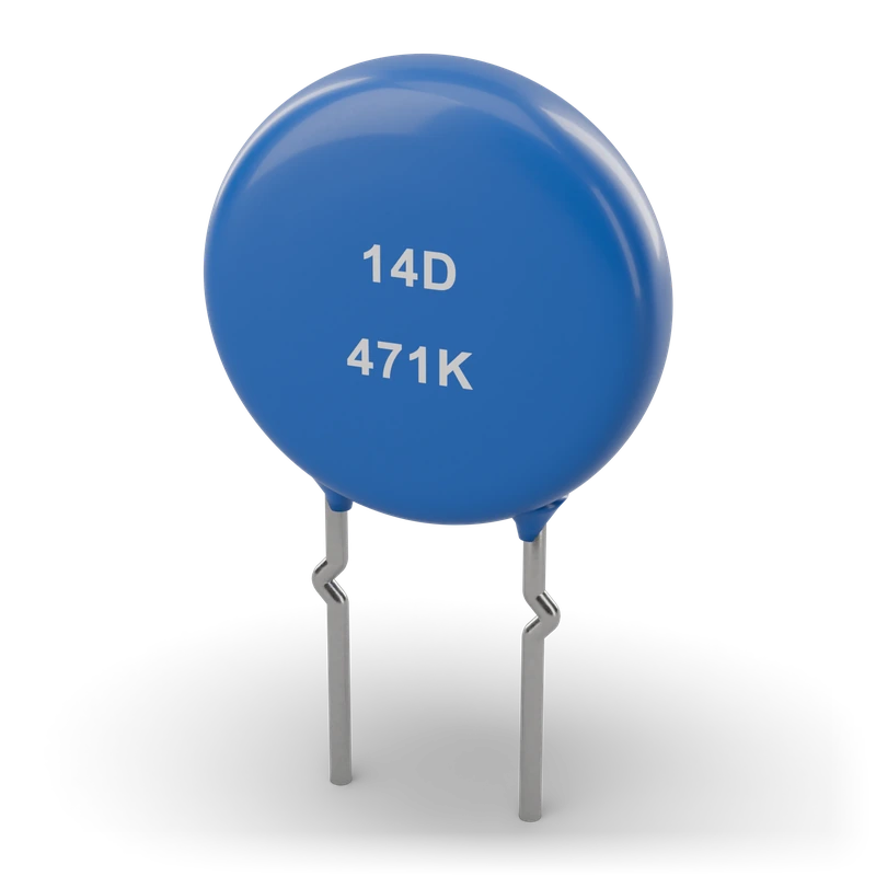 VaristorΩ · Resistance
Capacitors
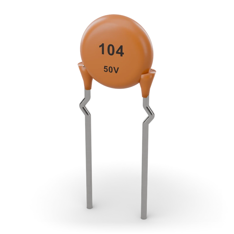
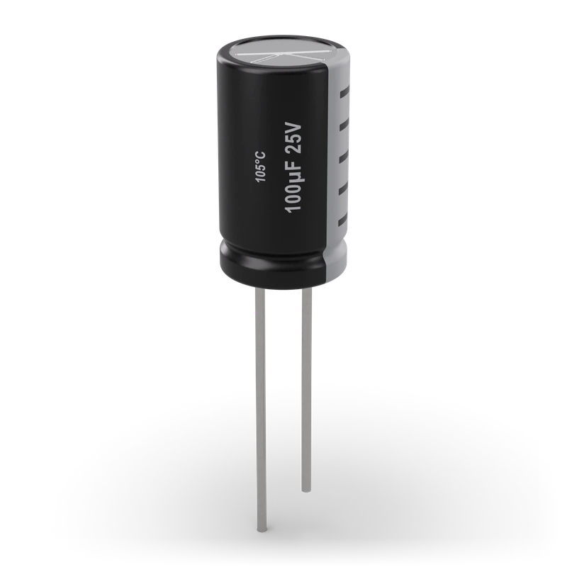
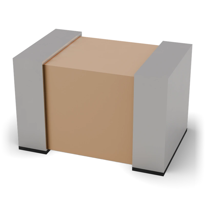
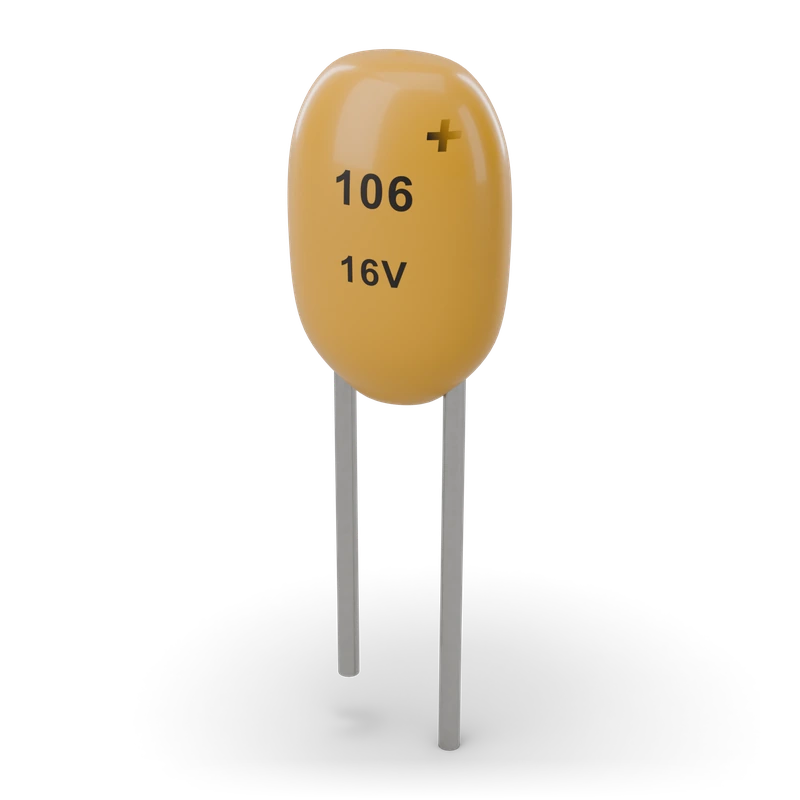
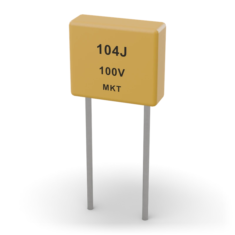
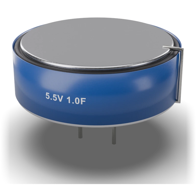
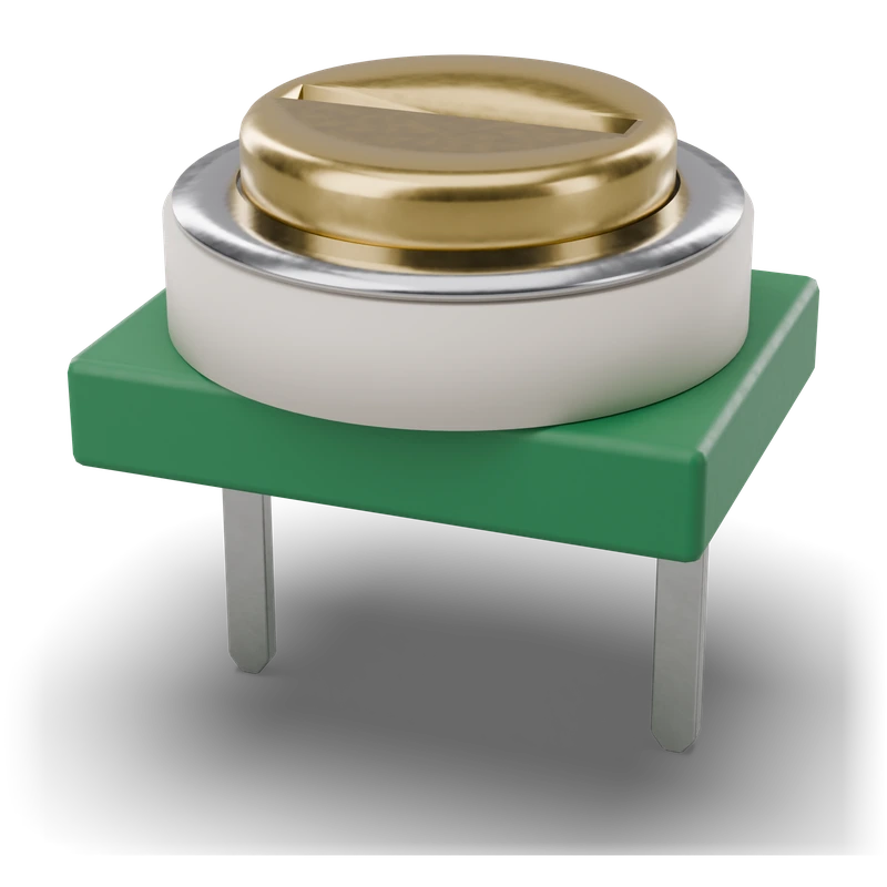
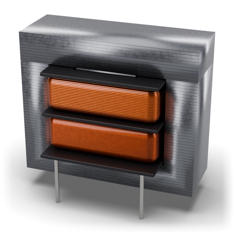
Inductors and transformers
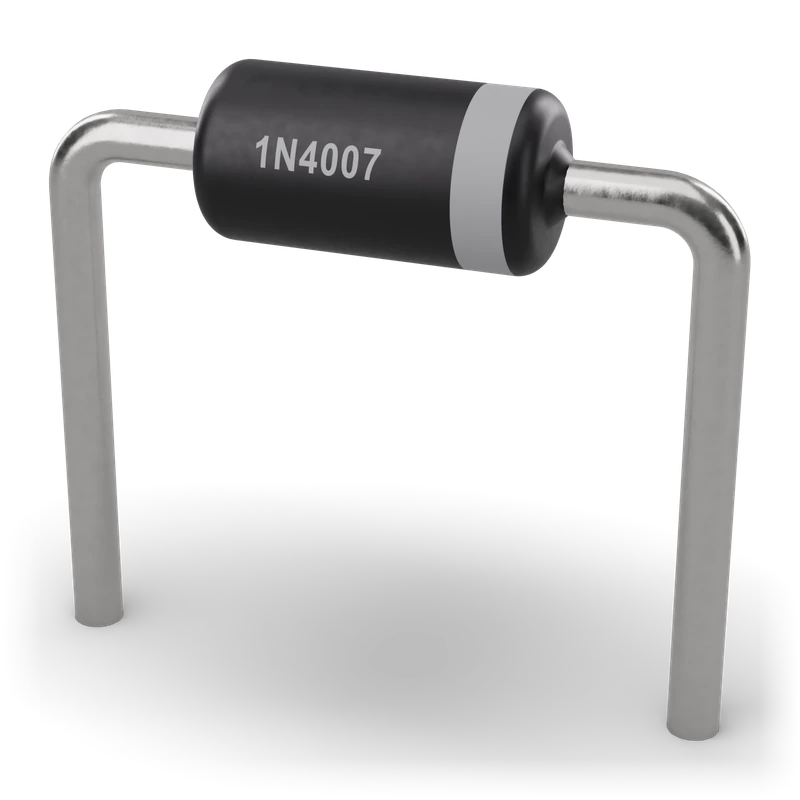
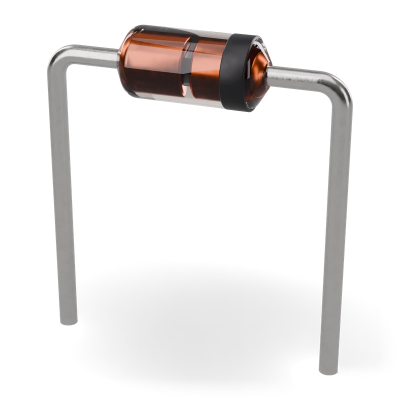
Diodes
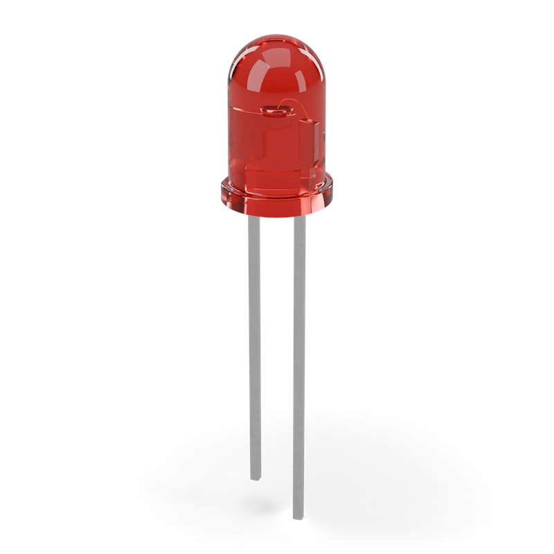
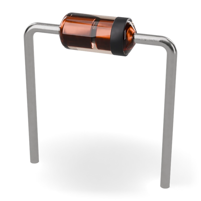
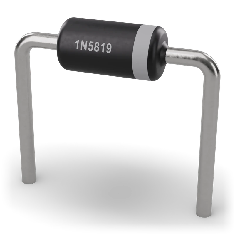
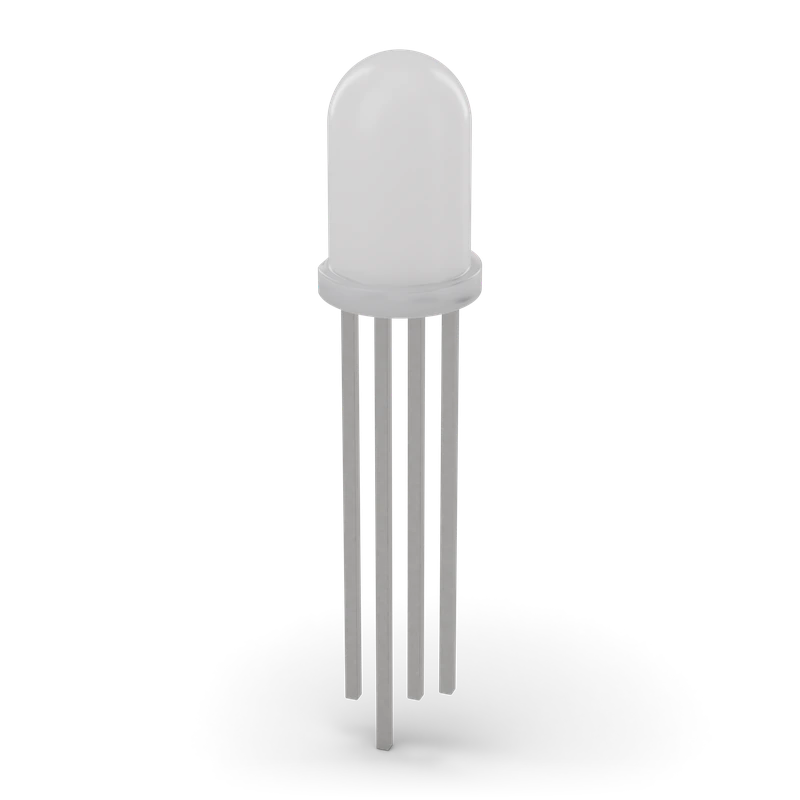
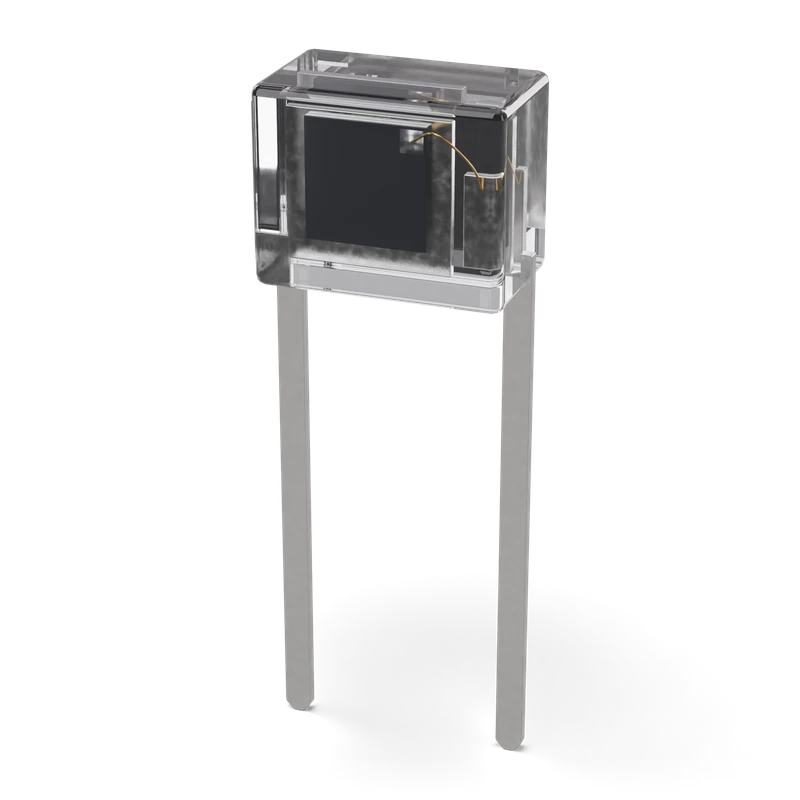
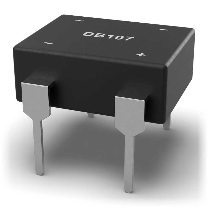
Transistors
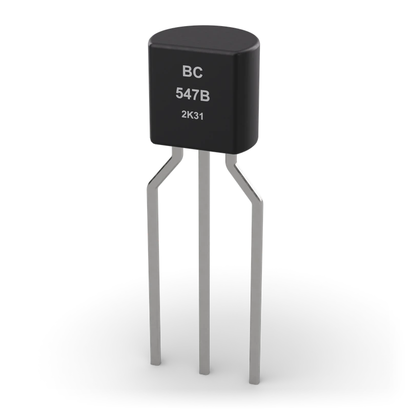
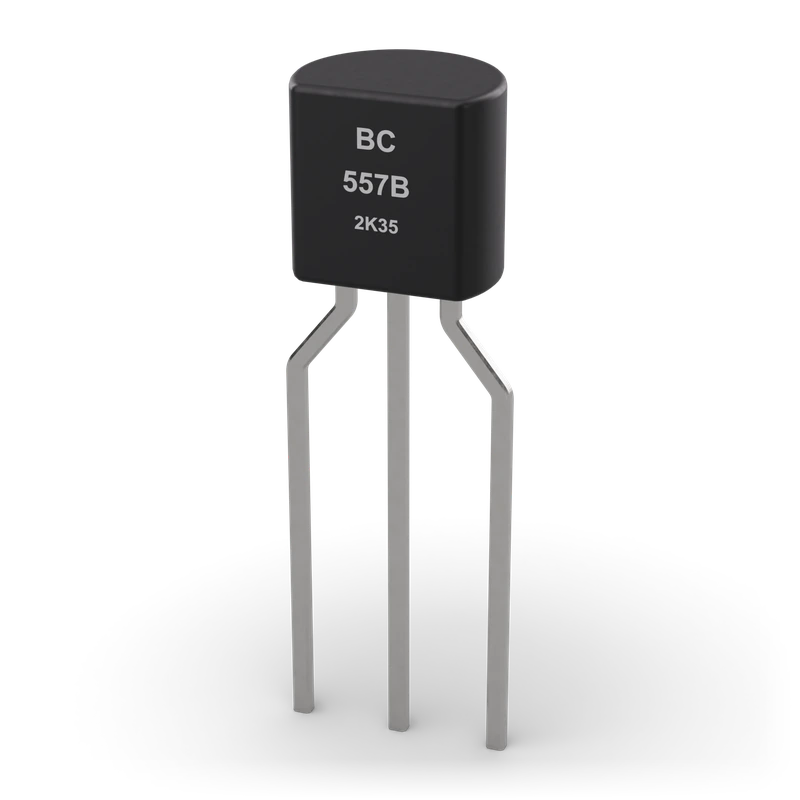
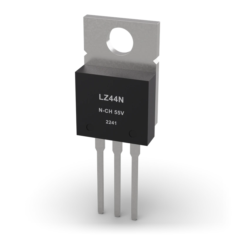
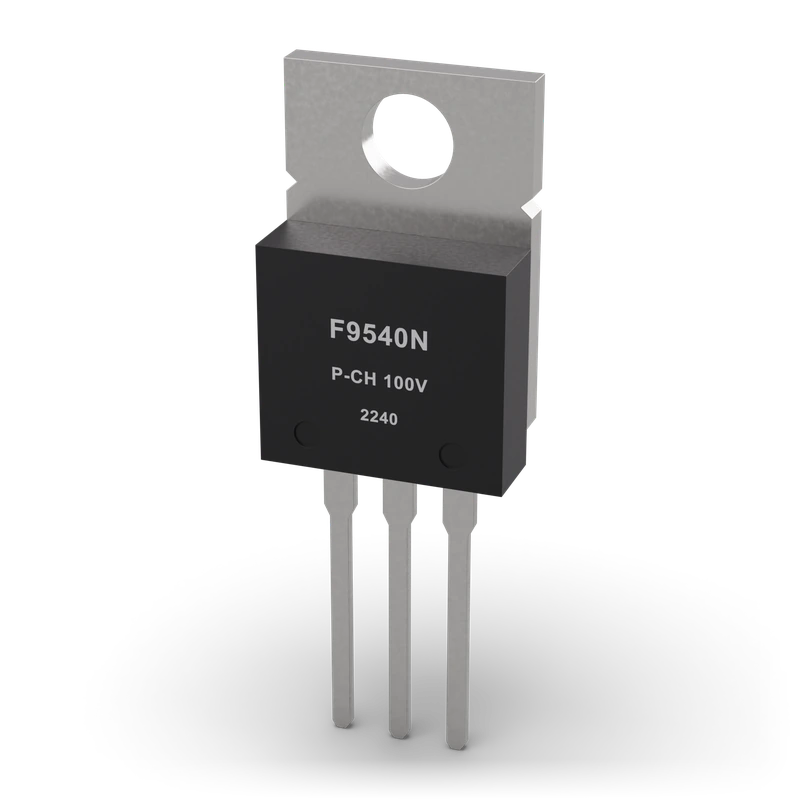
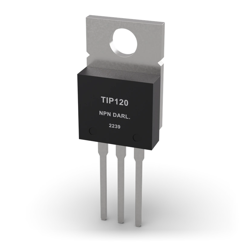
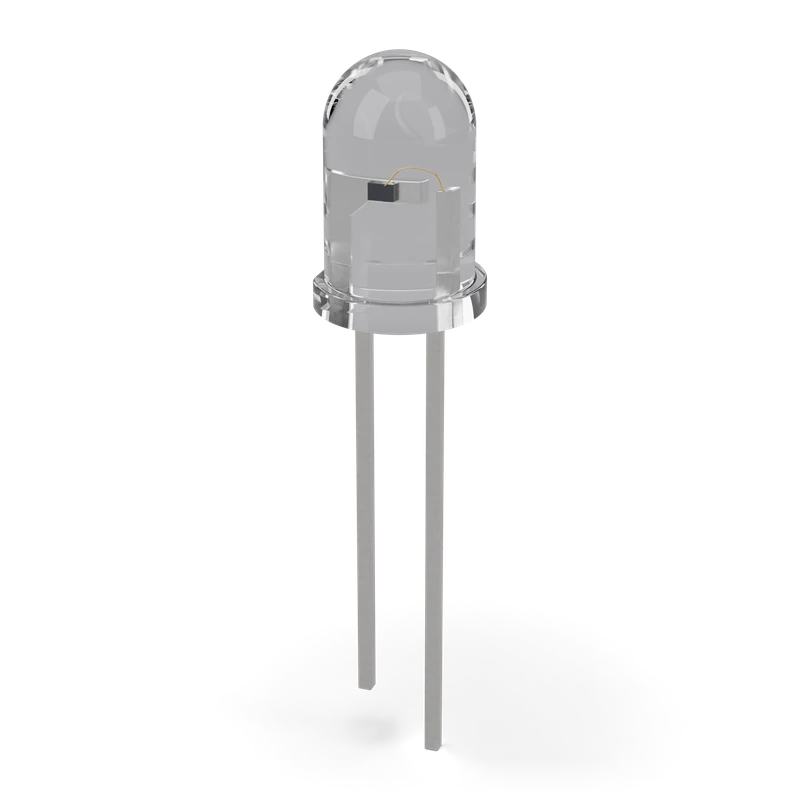
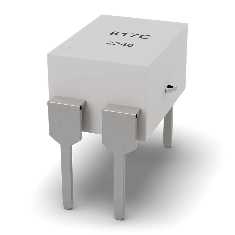
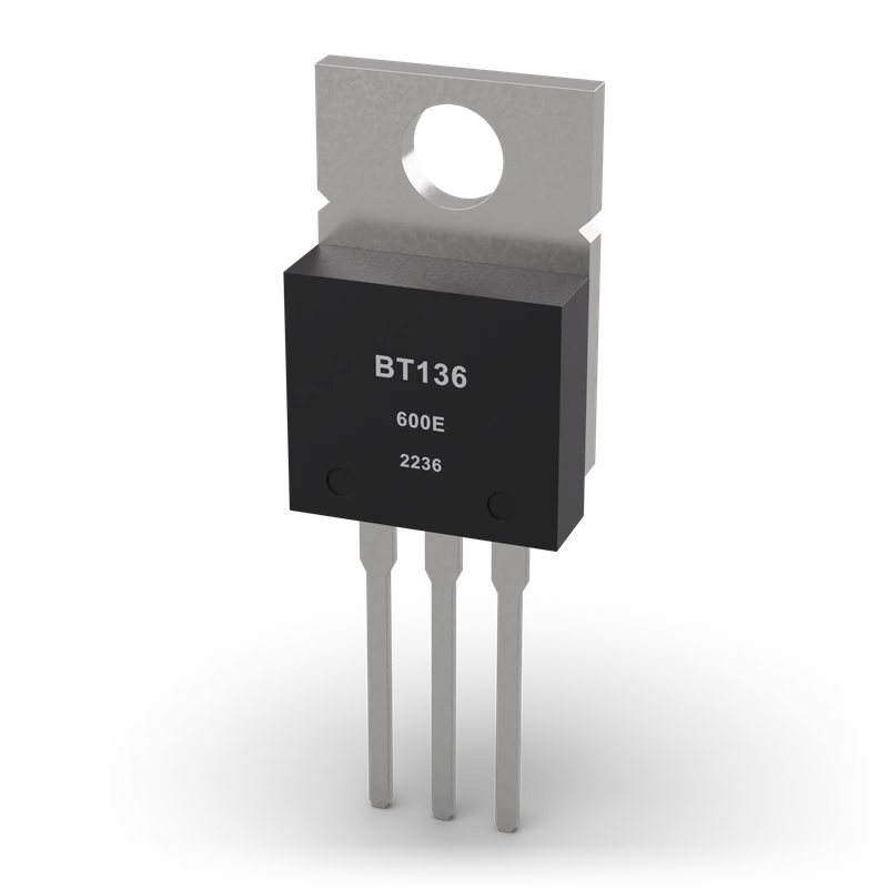
Power
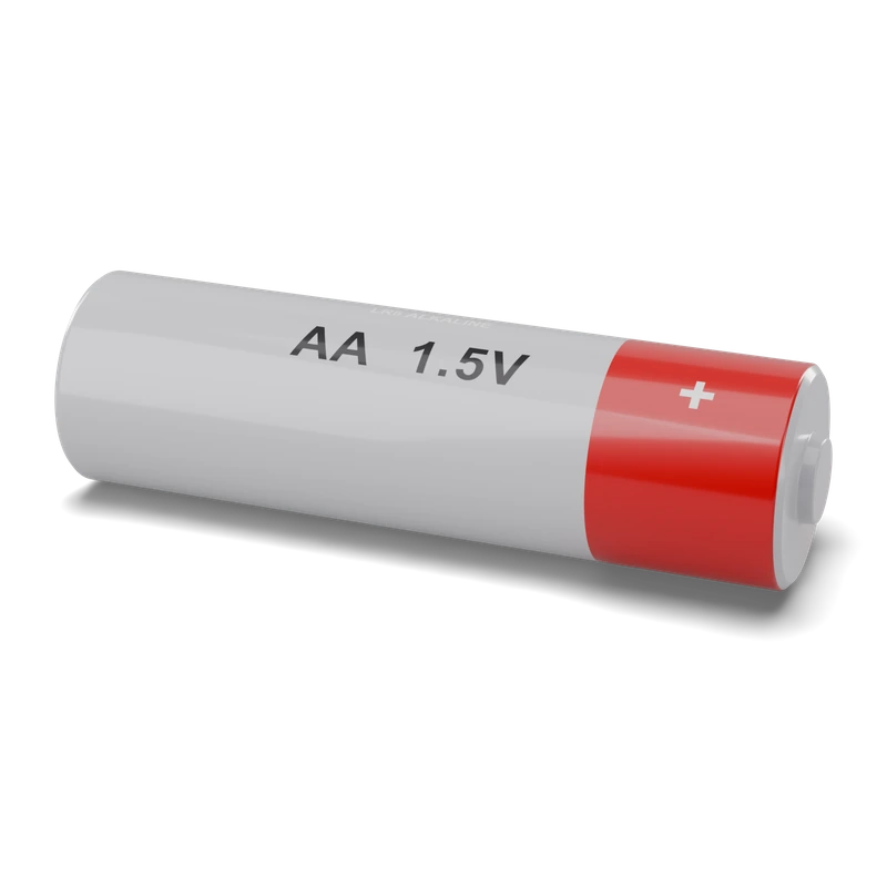 AA batteryV⎓ · DC voltage
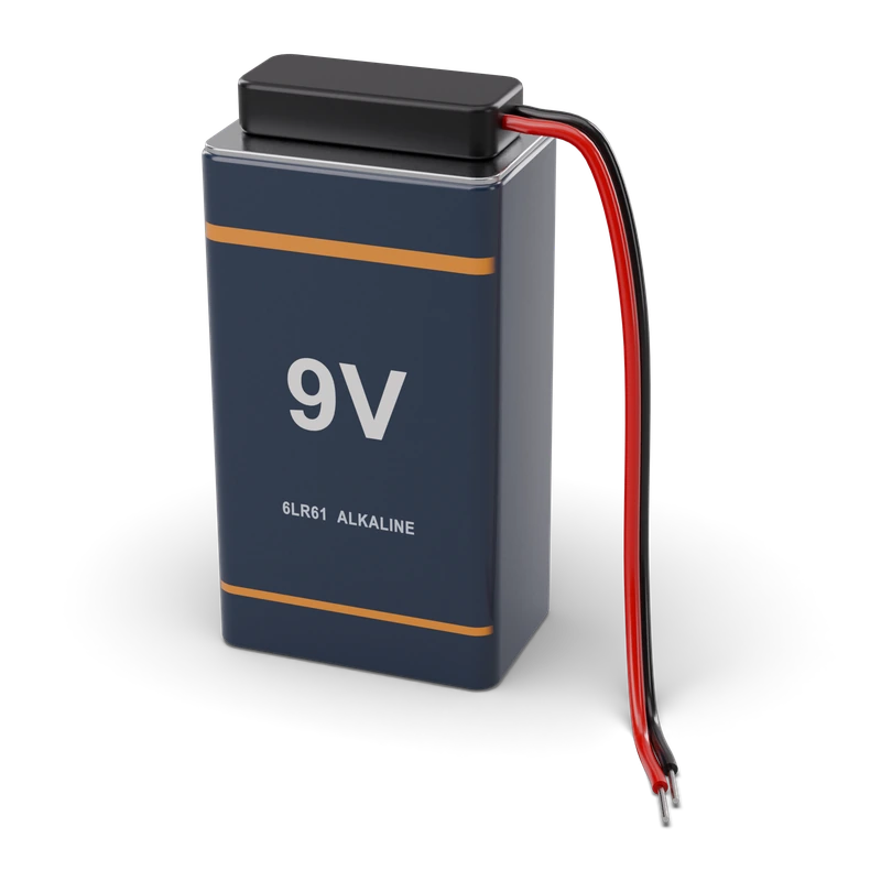 9 V batteryV⎓ · DC voltage
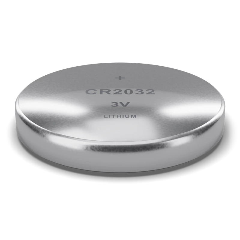 Coin cell (CR2032)V⎓ · DC voltage
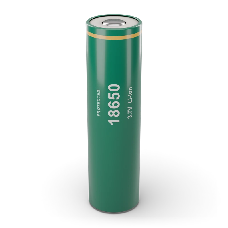 Li-ion cell (18650)V⎓ · DC voltage
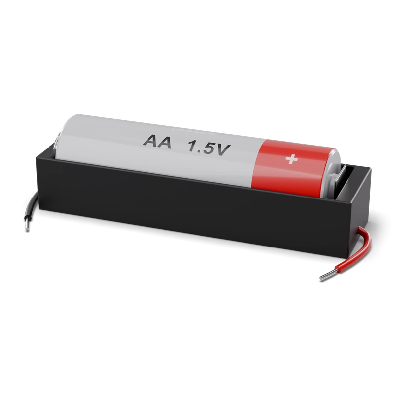 Battery holderV⎓ · DC voltage
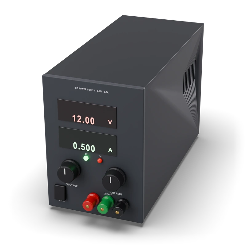 Lab power supplyΩ · Resistance
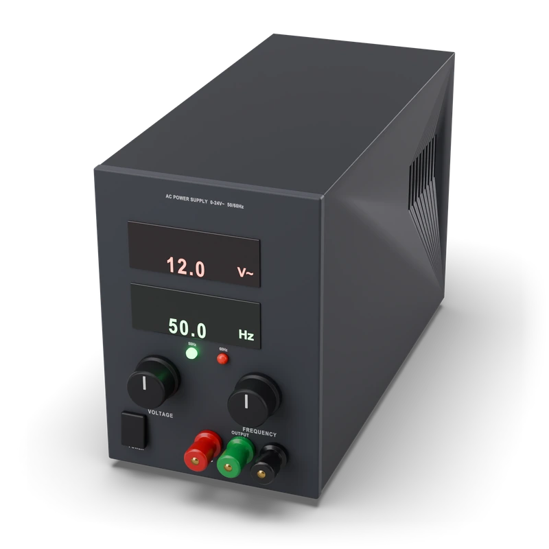 AC source (12 V~ 50 Hz adapter / signal generator)V~ · AC voltage
Current source (constant current, bench CC mode)mA⎓ · DC current (mA)